วันศุกร์ที่ 8 มีนาคม พ.ศ. 2562

mini project 2/2

วิธีใช้ I2C Communication ใน STM32 Microcontroller

แผนภาพวงจรและการเชื่อมต่อ

Circuit Diagram สำหรับการใช้ I2C Communication ใน STM32 Microcontroller

คำอธิบายการเขียนโปรแกรม Master STM32

ใน Master STM32 มาดูกันว่ามีอะไรเกิดขึ้น:
1. ก่อนอื่นเราต้องรวมไลบรารี่ของ Wire และ softwire ไลบรารี่เพื่อใช้ฟังก์ชั่นการสื่อสาร I2C ใน STM32F103C8
#include <Wire.h>     
#include <SoftWire.h>                      

2. ในการตั้งค่าโมฆะ ()
  • เราเริ่มการสื่อสารแบบอนุกรมที่ Baud Rate 9600
Serial.begin (9600);     
          
  • ต่อไปเราจะเริ่มการสื่อสาร I2C ที่พิน (B6, B7)
Wire.begin ();       

3. In Void loop ()
  • ก่อนอื่นเราจะได้รับข้อมูลจาก Slave Arduino ดังนั้นเราจึงใช้requestFrom ()กับ slave address 8 และเราขอหนึ่ง byte
Wire.requestFrom (8,1);                           

ค่าที่ได้รับถูกอ่านโดยใช้Wire.read ()
byte a = Wire.read();            

  • ขึ้นอยู่กับค่าที่ได้รับจาก Slave LED หลักถูกเปิดหรือปิดโดยใช้การเขียนแบบดิจิตอลที่พิน PA1 และการพิมพ์แบบอนุกรมใช้เพื่อพิมพ์ค่าในมอนิเตอร์แบบอนุกรม
if (a == 1)                             
      { 
      digitalWrite (LED, HIGH); 
      Serial.println ("เปิดไฟ LED หลัก"); 
      } 
    else 
      { 
      digitalWrite (LED, LOW); 
      Serial.println ("ปิดไฟ LED หลัก"); 
      }

  • ต่อไปเราต้องอ่านสถานะของพิน PA0 นั่นคือปุ่มกด STM32 หลัก
int pinvalue = digitalRead (buttonpin);
   
  •  ถัดไปส่งค่าพินตามลอจิกดังนั้นเราจะใช้ถ้าเงื่อนไขแล้วเริ่มส่งด้วยอาร์ดิโนสลาฟด้วย 8 เป็นที่อยู่แล้วเขียนค่าตามค่าอินพุตปุ่มกด
if (pinvalue == HIGH)                          
    { 
      x = 1;

    }    
  else 
   { 
      x = 0; 

    }
 
Wire.beginTransmission (8);                           
Wire.write (x);                        
Wire.endTransmission ();                 

คำอธิบายการเขียนโปรแกรม Slave Arduino

1. ก่อนอื่นเราต้องรวมไลบรารี่ของ Wire สำหรับการใช้ฟังก์ชั่นการสื่อสาร I2C
#include <Wire.h>    
              
2. ในการตั้งค่าโมฆะ ()
  • เราเริ่มการสื่อสารแบบอนุกรมที่ Baud Rate 9600
Serial.begin (9600);                

  • ถัดไปเริ่มการสื่อสาร I2C ที่พิน (A4, A5) พร้อมที่อยู่สลาฟเป็น 8 ที่นี่เป็นสิ่งสำคัญที่จะต้องระบุที่อยู่สลาฟ                                         
 Wire.begin (8);       

ต่อไปเราต้องเรียกฟังก์ชันWire.onReceiveเมื่อ Slave ได้รับค่าจาก master และWire.onRequestเรียกใช้ฟังก์ชันเมื่อ Master ร้องขอค่าจาก Slave
Wire.onReceive (receiveEvent); Wire.onRequest (requestEvent);           

3. ถัดไปเรามีสองฟังก์ชั่นหนึ่งสำหรับกิจกรรมร้องขอและอีกหนึ่งฟังก์ชั่นสำหรับรับเหตุการณ์ 

สำหรับการร้องขอกิจกรรม
เมื่อ Master STM32 ร้องขอค่าจาก Slave ฟังก์ชันนี้จะทำงาน ฟังก์ชั่นนี้ใช้ค่าอินพุตจากปุ่มกด Slave Arduino และส่งไบต์ (1 หรือ 0) ไปยัง Master STM32 ตามค่าปุ่มกดโดยใช้Wire.write ()
ถือเป็นโมฆะ requestEvent ()                          
  { 
  int value = digitalRead (buttonpin);         

  if (value == HIGH)                             
{ 
    x = 1; 
  } 
  else 
  { 
   x = 0; 
  } 
  Wire.write (x);                           
}

สำหรับรับเหตุการณ์
เมื่อ Master ส่งข้อมูลไปยังสลาฟพร้อมที่อยู่สลาฟ (8) ฟังก์ชั่นนี้จะทำงาน ฟังก์ชั่นนี้อ่านค่าที่ได้รับจากต้นแบบและเก็บในตัวแปรชนิดไบต์แล้วใช้ถ้าตรรกะเพื่อเปิดหรือปิด LED ทาสขึ้นอยู่กับค่าที่ได้รับ หากค่าที่ได้รับคือ 1 ไฟ LED จะติดและสำหรับ 0 LED จะดับ
void receiveEvent (int howMany)           
 {
  byte a = Wire.read();                     

  if (a == 1)                               

 {
   digitalWrite(LED,HIGH);
   Serial.println("Slave LED ON");

  }
  else
  {
    digitalWrite(LED,LOW);
    Serial.println("Slave LED OFF");
  }
  delay(500);
}
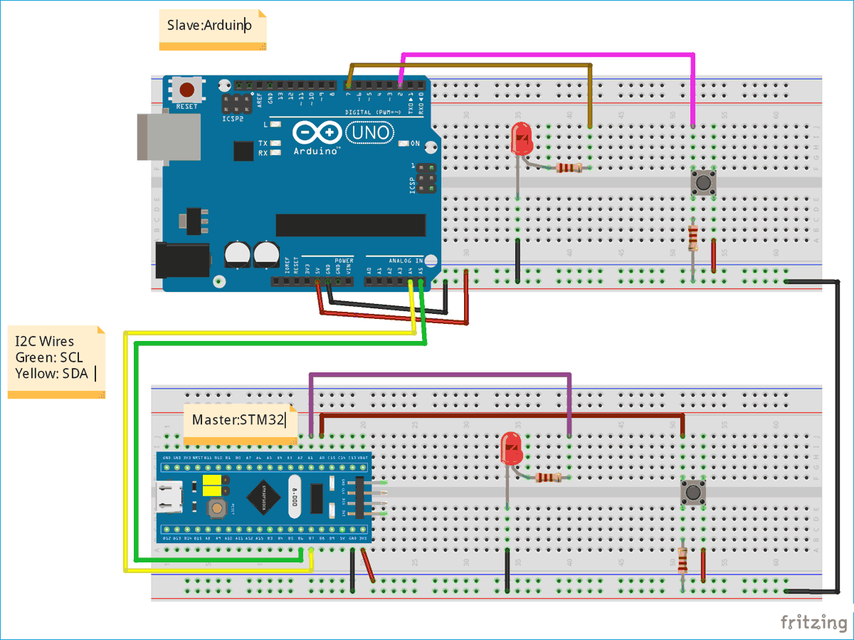
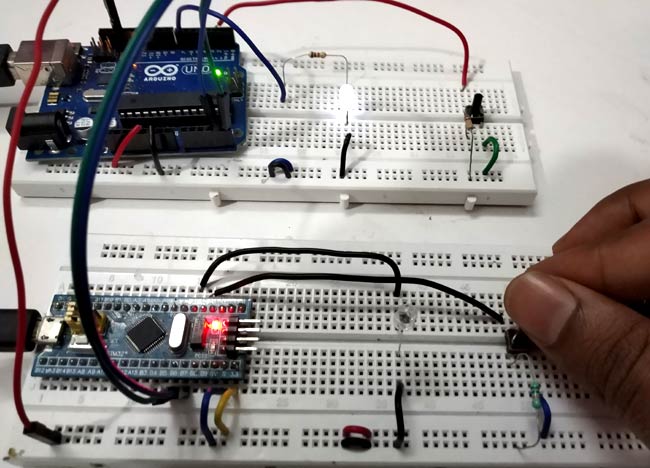
I2C Communication takes place in STM32

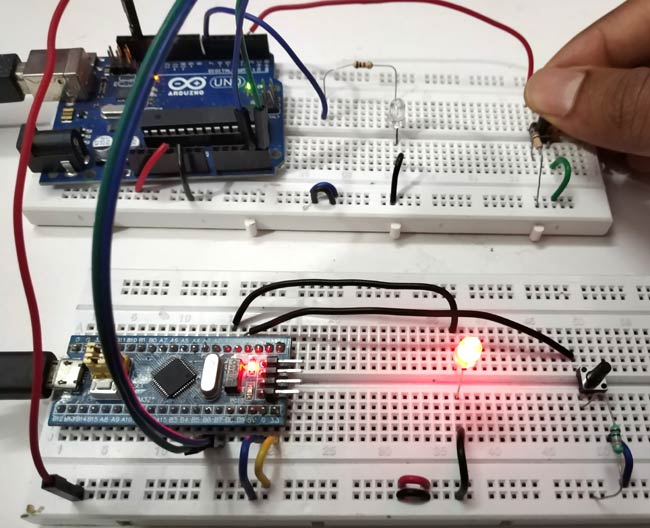
2. Now when we press the push button at Slave side, the LED connected to Master turns ON (Red) and when button is released LED turns OFF.
Connection between STM32 and Arduino using I2C

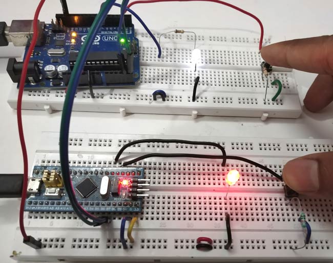
3. When both the push buttons pressed simultanewolsy, then both the LEDs glow at the same time, and remains ON until the buttons are pressed
Testing I2C Communication in STM32 Microcontroller

วันอาทิตย์ที่ 17 กุมภาพันธ์ พ.ศ. 2562

งานที่ 17 ตัวอย่างงานที่ใช้โปรแกรม Arduino สปที่ 17


ตัวอย่างงานที่ใช้โปรแกรม Arduino


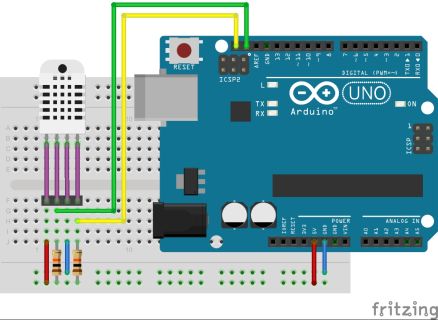
การใช้งาน AM2320 วัดค่า อุณหภูมิความชื่น ด้วยArduino


การใช้am2320 Arduino 2
Source code การใช้งาน AM2320 วัดค่า อุณหภูมิความชื่น ด้วยArduino
LIBRARY AM2320 : Download
#include <Wire.h>
#include <MyAM2320I2C.h>
MyAM2320I2C MyAM(0xB8 >> 1);
void setup()
{
Serial.begin(9600);
if(MyAM.isReady()) Serial.println(“AM2323 OK”);
else Serial.println(“AM2323 Fehler”);
void loop()
{
MyAM.readRaw()
Serial.println(MyAM.readHumidity());
Serial.println(MyAM.readTemp());
delay(5000);
}
 อ้างอิง :http://arduinoprojects.in.th/%E0%B8%81%E0%B8%B2%E0%B8%A3%E0%B9%83%E0%B8%8A%E0%B9%89%E0%B8%87%E0%B8%B2%E0%B8%99-am2320-%E0%B8%A7%E0%B8%B1%E0%B8%94%E0%B8%84%E0%B9%88%E0%B8%B2-%E0%B8%AD%E0%B8%B8%E0%B8%93%E0%B8%AB%E0%B8%A0%E0%B8%B9/

งานที่ 16 ตัวอย่างงานที่ใช้โปรแกรม Arduino สปที่ 16

ตัวอย่างงานที่ใช้โปรแกรม Arduino


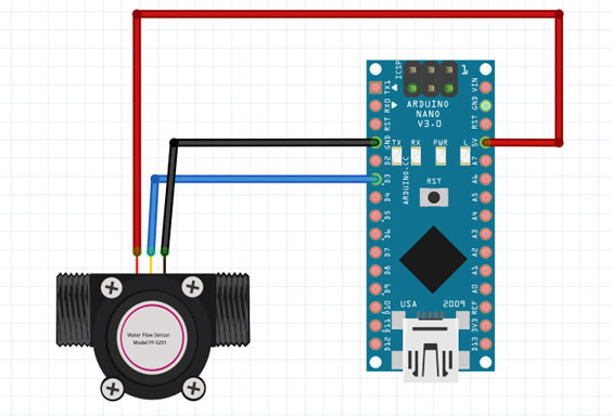
การใช้งาน Water Flow Sensor กับ Arduino
waterflow-sensor-arduino
ตัวอย่างโปรแกรม Water Flow Sensor กับ Arduino
volatile int flow_frequency;               // Water flow 
unsigned int l_hour,f_val;                 // Water flow  
unsigned long ctTime,flow_val,cloopTime;   // Water flow
void flow () //  Water flow Interrupt function
{
   flow_frequency++;  f_val++;
}
void setup()
{
   Serial.begin(9600);
   attachInterrupt(1, flow, RISING);  sei();   ctTime = millis();  cloopTime = ctTime; // Water flow
}
void loop ()
{
   ctTime = millis();
   if(ctTime >= (cloopTime + 1000))
   {
      cloopTime = ctTime;
      l_hour = (flow_frequency * 60 / 7.5);    
      flow_frequency = 0; 
      Serial.print(l_hour, DEC);     Serial.print(" L/hour");      
   }
   if(f_val>=450){flow_val++;f_val=0;}
   Serial.println(flow_val);Serial.println("L"); 
   
} 
อ้างอิง : http://arduinoprojects.in.th/%E0%B8%81%E0%B8%B2%E0%B8%A3%E0%B9%83%E0%B8%8A%E0%B9%89%E0%B8%87%E0%B8%B2%E0%B8%99-water-flow-sensor-%E0%B8%81%E0%B8%B1%E0%B8%9A-arduino/ 

งานที่ 15 ตัวอย่างงานที่ใช้โปรแกรม Arduino สปที่ 15

ตัวอย่างงานที่ใช้โปรแกรม Arduino


Arduino ควบคุม DC Motor ด้วย L298

Arduino ควบคุมMotor ผ่าน L298
Source Code Arduino ควบคุม Motor ด้วย L298 Module
int IN1 = 4;
int IN2 = 5;
int IN3 = 6;
int IN4 = 7;
 
void setup()
{
 
 pinMode(IN1, OUTPUT);
 pinMode(IN2, OUTPUT);
 pinMode(IN3, OUTPUT);
 pinMode(IN4, OUTPUT);
}
 
void loop()
{
 digitalWrite(IN1, HIGH);
 digitalWrite(IN2, LOW);
 delay(2000);
 digitalWrite(IN1, HIGH);
 digitalWrite(IN2, HIGH);
 delay(500);
 digitalWrite(IN3, HIGH);
 digitalWrite(IN4, LOW);
 delay(2000);
 digitalWrite(IN3, HIGH);
 digitalWrite(IN4, HIGH);
 delay(500);
 digitalWrite(IN1, LOW);
 digitalWrite(IN2, HIGH);
 delay(2000);
 digitalWrite(IN1, HIGH);
 digitalWrite(IN2, HIGH);
 delay(500);
 digitalWrite(IN3, LOW);
 digitalWrite(IN4, HIGH);
 delay(2000);
 
 digitalWrite(IN3, HIGH);
 digitalWrite(IN4, HIGH);
 delay(500);
อ้างอิง : http://arduinoprojects.in.th/arduino-%E0%B8%84%E0%B8%A7%E0%B8%9A%E0%B8%84%E0%B8%B8%E0%B8%A1-dc-motor-%E0%B8%94%E0%B9%89%E0%B8%A7%E0%B8%A2-l298/

งานที่ 14 ตัวอย่างงานที่ใช้โปรแกรม Arduino สปที่ 14

ตัวอย่างงานที่ใช้โปรแกรม Arduino

อบรม arduino การใช้งานพื้นฐานเชื่อมต่อ labview และ IoT ง่าย


PIR Motion Sensor Detector Module HC-SR501

int pirPin = 2; //digital 2
intLedPin = 13;
void setup(){
Serial.begin(9600);
pinMode(pirPin, INPUT);
pinMode(LedPin,OUTPUT);
}
void loop(){
int pirVal = digitalRead(pirPin);
if(pirVal == LOW){ //was motion detected
digitalWrite(LedPin,HIGH);
delay(2000);
}
else
{
digitalWrite(LedPin,LOW);
}
}
อ้างอิง : http://arduinoprojects.in.th/%E0%B8%81%E0%B8%B2%E0%B8%A3%E0%B9%83%E0%B8%8A%E0%B9%89%E0%B8%87%E0%B8%B2%E0%B8%99-pir-motion-sensor-detector-module-hc-sr501/


งานที่ 13 ตัวอย่างงานที่ใช้โปรแกรม Arduino สปที่ 13

ตัวอย่างงานที่ใช้โปรแกรม Arduino


ESP8266 / ESP8285 กับการส่งการแจ้งเตือนเข้า LINE


#include <ESP8266WiFi.h>
#include <WiFiClientSecureAxTLS.h> // กรณีขึ้น Error ให้เอาบรรทัดนี้ออก
// Config connect WiFi
#define WIFI_SSID "YOUR WIFINAME"
#define WIFI_PASSWORD "YOUR WIFIPASSWORD"
// Line config
#define LINE_TOKEN "LINE ACCESS TOKEN"
#define SW D2
String message = "โดนกด"; // ArduinoIDE เวอร์ชั่นใหม่ ๆ ใส่ภาษาไทยลงไปได้เลย
void setup() {
pinMode(SW, INPUT);
Serial.begin(9600);
WiFi.mode(WIFI_STA);
// connect to wifi.
WiFi.begin(WIFI_SSID, WIFI_PASSWORD);
Serial.print("connecting");
while (WiFi.status() != WL_CONNECTED) {
Serial.print(".");
delay(500);
}
Serial.println();
Serial.print("connected: ");
Serial.println(WiFi.localIP());
}
void loop() {
if (digitalRead(SW) == HIGH) {
while(digitalRead(SW) == HIGH) delay(10);
Serial.println("Enter !");
Line_Notify(message);
// Serial.println();
}
delay(10);
}
void Line_Notify(String message) {
axTLS::WiFiClientSecure client; // กรณีขึ้น Error ให้ลบ axTLS:: ข้างหน้าทิ้ง
if (!client.connect("notify-api.line.me", 443)) {
Serial.println("connection failed");
return;
}
String req = "";
req += "POST /api/notify HTTP/1.1\r\n";
req += "Host: notify-api.line.me\r\n";
req += "Authorization: Bearer " + String(LINE_TOKEN) + "\r\n";
req += "Cache-Control: no-cache\r\n";
req += "User-Agent: ESP8266\r\n";
req += "Connection: close\r\n";
req += "Content-Type: application/x-www-form-urlencoded\r\n";
req += "Content-Length: " + String(String("message=" + message).length()) + "\r\n";
req += "\r\n";
req += "message=" + message;
// Serial.println(req);
client.print(req);
delay(20);
// Serial.println("-------------");
while(client.connected()) {
String line = client.readStringUntil('\n');
if (line == "\r") {
break;
}
//Serial.println(line);
}
// Serial.println("-------------");
}
การทดสอบ
หลังจาก ESP8266 เชื่อมต่อ WiFi ได้แล้ว ทดลองกดสวิตซ์ จะมีข้อความว่า "โดนกด" มาปรากฏในห้องแชทของ LINE Notify เป็นอันจบการทดสอบ
อ้างอิง : https://www.ioxhop.com/article/47/esp8266-esp8285-%E0%B8%81%E0%B8%B1%E0%B8%9A%E0%B8%81%E0%B8%B2%E0%B8%A3%E0%B8%AA%E0%B9%88%E0%B8%87%E0%B8%81%E0%B8%B2%E0%B8%A3%E0%B9%81%E0%B8%88%E0%B9%89%E0%B8%87%E0%B9%80%E0%B8%95%E0%B8%B7%E0%B8%AD%E0%B8%99%E0%B9%80%E0%B8%82%E0%B9%89%E0%B8%B2-line